An example of a connective which is not associative is
• (A) AND • (C) EX-OR • (B) OR • (D) NAND
AND gate
An AND gate is a digital logic gate that performs a logical AND operation.
It has two or more inputs and one output.
The output of an AND gate is only 1 (or “true”) when all of its inputs are 1.
If any of the inputs are 0 (or “false”), the output will be 0.
An AND gate is often used to combine multiple signals or conditions to perform a specific function or operation.
For example, an AND gate may be used to turn on a light only when two separate switches are both in the on position.
The AND and OR gates are both commutative and associative.
For the AND function • AB = BA → Commutative • (AB)C = A(BC) = ABC Associative
EX-OR gate
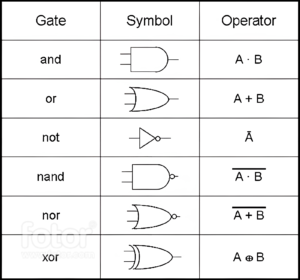
An EX-OR gate is a digital logic gate that performs exclusive disjunction.
It has two inputs and one output.
The output of an EX-OR gate is 1 if exactly one of the inputs is 1, and 0, if both inputs are 0 or both inputs, are 1.
In other words, the output is 1 if the inputs are different, and 0 if the inputs are the same.
The truth table for an EX-OR gate is as follows:
Input 1
Input 2
Output
0
0
0
0
1
1
1
0
1
1
1
0
EX-OR gates are often used in digital circuits to perform error detection and correction, and to implement Boolean functions such as addition and multiplication. They can also be used to implement gates such as AND and OR by using multiple EX-OR gates and inverters.
OR gate
An OR gate is a digital logic gate that performs an OR operation. It has two or more input signals and one output signal.
When any of the input signals is “1” (high), the output signal is “1” (high). If all the input signals are “0” (low), the output signal is “0” (low).
The OR gate is often represented by the symbol “|” or a triangle with a line underneath.
It is commonly used in circuit design to combine multiple signals into a single output.
NAND gate
A NAND gate is a digital logic gate that performs a NOT-AND operation.
It has two or more input terminals and one output terminal. When all of the input terminals are high (logic 1), the output is low (logic 0).
If any of the input terminals are low (logic 0), the output will be high (logic 1).
The NAND gate is the inverse of the AND gate, meaning that if the AND gate’s output is high, the NAND gate’s output will be low, and vice versa.
The NAND gate is often used in circuits as a universal gate, meaning it can be used to implement any other type of logic gate.